
Speaker Builder magazine
Croft review of Sahyoun Patent

Patent by Joseph Sahyoun, president of Earthquake Sound
Passive Acoustic Radiator Module Patent/Publication Number: 10,349,166 Inventor(s): Joseph Yaacoub Sahyoun; (Redwood City, CA)
Assignee: None
Listed Filed: May 26, 2016
Current International Class: H04R 1/22 (20060101)
Published: July 9, 2019
Number of Claims: 29
Number of Drawings: 44
Abstract from Patent A low-cost/high-efficiency passive radiator module component includes: a ported cavity structure adapted for placement inside an acoustic enclosure with a port communicating out of the acoustic enclosure and one or more pairs of passive radiators symmetrically oriented and supported on opposing side walls of the ported cavity each having a predetermined or tuned mass distribution, stiff acoustic radiating diaphragm surfaces, and spaced apart inner and outer suspensions configured to suppress diaphragm wobble that induces each pair to symmetrically vibrate inertially responsive to variable sound pressure pulses originating from an active acoustic radiator within the acoustic enclosure. Different variable acoustic pressure pulses may be detected inside and outside the ported cavity; the constricting horn connecting to the ported cavity from outside may be tuned by horn loading to achieve a desired effect.
Independent Claims 1. A passive acoustic radiator module comprising: a ported cavity structure adapted for placement inside an acoustic enclosure, to receive .+-.pressures from an air spring, the ported cavity structure being closed except for a horn structure having a throat section with a mouth section
Figure 2: A folded version of the lowest frequency port of the enclosure to increase acoustic mass and lower the tuning frequency
Figure 3: Configuration of the inter-chamber port with a baffle flange in front of the port 26 VOICE COIL communicating out of the acoustic enclosure, the throat section providing pressure resistance creating a different variable acoustic pressure inside and outside the throat section, the ported cavity structure having a plurality of walls and an opening therein, wherein, said opening is configured to be positioned in and sealed to a module receiving opening in the acoustic enclosure in which said module is to be operated and at least two substantially matched symmetrical acoustic radiating surfaces fixed to radiators having a predetermined mass distribution are suspended in at least two walls of said plurality of walls so that vibration of these at least two radiating surfaces cause a sound pressure level change through said opening.
5. A passive acoustic radiator module component comprising: a ported cavity structure adapted for placement inside an acoustic enclosure, to receive .+-. pressures from an air spring, the ported cavity structure having a horn structure having a throat section with a mouth section communicating out of the acoustic enclosure, the throat section providing pressure resistance creating a different variable acoustic pressure inside and outside the throat section, the ported cavity structure having an inner space surrounded by a plurality of walls and a mouth opening, wherein a radiating surface is suspended from at least one of said plurality of walls using a suspension surround arrangement.
6. A passive radiator module mountable in an acoustic enclosure comprising: a ported cavity structure adapted for placement inside an acoustic enclosure, to receive .+-. pressures from an air spring, the ported cavity structure being closed except for a horn structure having a throat section with a mouth section communicating out of the acoustic enclosure, the throat section providing pressure resistance creating a different variable acoustic pressure inside and outside the throat section, the ported cavity structure having an inner space surrounded by a plurality of walls and a mouth opening, wherein a radiating surface is suspended from at least one of said plurality of walls using a suspension surround arrangement; an active acoustic radiator, capable of radiating variable acoustic pressure pulses within the acoustic enclosure for enhancing acoustic output comprising, in combination: a walled structure having a cavity therein, the walled structure having a radiator wall of a predetermined mass suspended within a flexible surround, whereby, said radiator wall is induced to vibrate responsive to variable acoustic pressure pulses radiated by the active acoustic radiator within said acoustic enclosure.
7. A passive acoustic radiator module component comprising: a ported cavity structure adapted for placement inside an acoustic enclosure, to receive .+-. pressures from an air spring, the ported cavity structure being closed except for a horn structure open to the outside having a throat section providing pressure resistance creating a different variable acoustic pressure inside and outside the throat section, the ported cavity structure having an inner space surrounded by a plurality of walls and the mouth opening, wherein a radiating surface is suspended from at least one of said plurality of walls using a suspension surround arrangement.
Reviewer Comments The invention under review is the 21st US patent from the rather prolific and innovative Joseph Sahyoun, founder of Earthquake Sound. While Sahyoun’s previous works have including aspects of both loudspeakers and power amplification, the majority of his intellectual property has been directed toward various forms of passive diaphragm radiators, and his most recent effort in this category is the focus of this review.
Passive diaphragm radiators, originally referred to as “Drone Cones,” were used as a substitute for the acoustic mass of a port/vent in a bass reflex loudspeaker, and were first patented by Harry F. Olson at Radio Corp. of America in 1935, published as US 1,988,250, “Loudspeaker and method of propagating sound,” just two years after Albert Thuras of Bell Labs was granted a patent on the original “ported” bass reflex loudspeaker. The first technical disclosure provided by Olson, John Preston, and Everett May, in October 1954 issue of the Journal of the Audio Engineering Society, (Volume 2, No. 4, p. 219), “Recent Developments in Direct-Radiator High-Fidelity Loudspeakers.” The original notion that drove the passive radiator development of Olson, et al. in 1954 was that the conventional Helmholtz-bass-reflex loudspeaker, with an open port providing the acoustic mass, was determined to have port particle velocity that was not uniform and that it was also fraught with viscous losses, particularly in the smaller diameter, elongated versions.
Therefore, it was thought that a suspended diaphragm, passive radiator of equivalent acoustic mass, would be a superior device, and “initial” frequency response measurements were shown to support the idea that the passive diaphragm radiator was superior, exhibiting more extended low-frequency capability. It wasn’t until 20 years later, when Richard Small, in his famous Audio Engineering Society (AES) papers on the Vented Loudspeakers, (more specifically his “PassiveRadiator Loudspeaker Systems: Analysis and Synthesis,” Journal of the Audio Engineering Society, Volume 22, Issues 8 and 9) explored the passive radiator more thoroughly than Olson, showed that it was not superior to an optimally designed ported equivalent. In fact, in most cases, it was slightly inferior, due to the addition of the compliance parameter in the passive radiator suspension. To the extent that the passive radiator had less than infinite compliance, it developed a notch in the high-pass characteristic, causing a steeper initial high-pass slope and reduction in output near the cut-off frequency.
Ultimately, the passive radiator has been useful, particularly where the enclosure volume is small enough to where a vent that is properly sized for high performance requires too much additional enclosure volume, and a vent that is small enough to be practical, has too much distortion, losses, and audible turbulence to be acceptable. So, in small and/or high output bass reflex enclosures, welldesigned passive diaphragm radiators have been found to be a practical and effective vent/port substitute. The inventor of the current patent has spent a couple decades developing enhanced passive diaphragm radiators to stabilize their movement and avoid diaphragm “tilt or wobble” during significant diaphragm excursions. Some examples of Sahyoun’s previous work can be found in his US Patent No. 6,044,925; US Patent No. 6,460,651; US Patent No. 6,626,263; US Patent No. 7,318,496; US Patent No. 7,360,626; and US Patent No. 8,204,269, wherein Sahyoun teaches a necessity for, and advantages of, symmetrically loaded suspension systems for both active and passive acoustic radiator systems characterized as Symmetrically Loaded Audio Passive Systems or the Earthquake Sound (SLAPS). A description of this invention might be that of using two or more of the previous Sahyoun multiple suspension system passive radiators (SLAPS) in opposition and having their output exit to the external environment through a duct or port.
A first basic example of the invention can be seen in Figure 4, where two passive diaphragms 139 face each other and are driven from their outside surfaces and their outputs sum together into a common duct and exit through the duct opening 143. It can be seen that the inner, stabilizing surrounds 141 have open areas to minimize stiffness and maintain high overall suspension compliance, while still providing improved stabilization of the moving system as compared to having only the outer, half-roll surrounds 137. This porting of the passive radiators to the external environment allows for a small faceprint output exit from the passive radiators, which may have large diameters and are inconvenient for mounting directly on the enclosure surface if the enclosure is small or has a narrow profile in at least one dimension. There have been other devices in the prior art that have internal passive radiators with an exit through a duct opening to the external environment, such as US Patent No. 7,133,533, by Geoffrey Chick, et al. “Passive Acoustic Radiating” assigned to Bose; and US Patent No. 10,341,765, by Shengbo Li, “Passive Radiator Assembly” assigned to Harman International. Sahyoun has several curious explanations for why those prior art systems are not as effective as his invention, such that they “are not easily tuned to provide an acceptable audible bass response much less a nuanced blend of subaudibly sensed vibrations.” He explains, “Depending how far a listener is from the source, he or she will viscerally sense resonance frequencies as low as 15 Hz from a source that has a fundamental source frequency of 41.2 Hz.
The generation of such sub-audible mechanical vibrations effectively brings a listener to center stage providing sensation of audible frequencies combined with a blend of low-frequency vibrations below audible, which can likely be detected by skin and other nerve ending detectors (sensors) of the human body.” There are some other concerns with the prior art that are discussed, such as: the notion that when using dualpassive radiators, there is a problem where their resonant frequencies may not be perfectly matched, for which it is suggested that anomalies such as multiple tuning frequencies and non-ideal passive radiator summation can occur. One issue that is interesting, that the invention addresses, is that of the pressure across the passive radiator being unequal from the inner portion of the duct to the exit of the duct, such that the passive radiator can tilt or wobble during long excursions. However, as can be seen in Figure 5, securing tuning masses 160, centered with respect to the mouth axis of the Passive Acoustic Radiator Module (PARM) is said to be able to reduce or damp the wobble. Since there are two radiating surfaces, each has a tuning mass offset from the center of mass of the stiff disks of the passive radiator 153. It is stated that: “These masses at least partially cancel the differential air mass loading on the front part of the radiating surface, slowing down the motion of the front part.
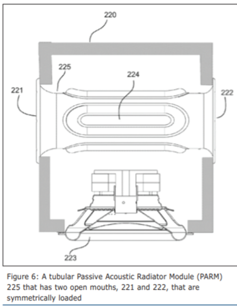
An acoustical designer can also position the tuning mass offset from a center position to alleviate wobble induced by other factors (e.g., as gravity when the PARM is angularly mounted). Gravity is a factor that affects the at-rest position of a moving masses and the inertial loading of the respective passive radiators of PARMs.” Figure 6 illustrates a tubular Passive Acoustic Radiator Module 225 that has two open mouths, 221 and 222, that are symmetrically loaded by four elongated passive radiators mounted around the circumference of the tubular duct. The vibratory element (diaphragm), 224, faces an equal resistance to the outside pressure at each end, optimizing symmetry and, therefore, doesn’t suffer the wobble described previously, eliminating the need to provide an “anti-wobble mass.” These opposing mouths allow for the air to move in and out of the tubular body of the PARM, potentially reducing turbulence, distortion and losses as compared to a single exit structure. This approach is similar in also providing the same interesting appearance of the Polk Audio “see-through” port that runs from the front to the back of the enclosure but with the twist of the ingress side channel port being replaced by passive radiators. (US Patent No. 7,162,049, “Ported loudspeaker system and method with reduced air turbulence, bipolar radiation pattern and novel appearance” by Matthew S. Polk, Jr.)
Figure 7 shows a cutaway of an enclosure 251, which has a speaker 250 radiating and loading a passive module, which has inner and outer surfaces 254 and 252, respectively. Unique to this embodiment, the two passive radiator surfaces are isolated from one another by a separation plane 253 which isolates or blocks any asymmetrical interaction between the two passive diaphragms, that might be caused by non-uniformity in manufacturing or any differentiated loading that may cause passive radiator “wobble.” It is stated that, “a further benefit of the arrangement shown in Figure 7 is the slanted “L” shape of the passive loading module. In this configuration, the passive radiator element mounted in the inner surface 254 facing the rear of the active speaker 250, directly receives, dampens and reflects directly the sound pressure received from the back of the active speaker 250. This arrangement reduces frequency phase distortion, which occurs in other configurations where the sound pressure waves must bounce off and reflect off angled and side surfaces.”
It is unlikely that these “phase distortion” effects are at issue, due to the very long wavelengths at the frequencies of operation for a subwoofer device such as this. But, it is clear that most of the disclosed embodiments may allow for a greater structural utility of using larger passive radiators for a given enclosure size or configuration, particularly, since passive radiators are most often a required replacement for an optimized port in enclosures that are smaller or that have unusual form factors. Considering the fact that the reasons that one usually replaces a vent with a passive radiator is to eliminate losses, distortion, pipe resonances, and exit turbulence, along with minimizing the cubic volume packaging impact of the vent size, it seems that the embodiment shown in Figure 7 might be less of a net gain and by way of introducing the elongated duct to the output of the passive radiators, it would seem that one has reintroduced the possibility of the linear and nonlinear distortions that can come from small diameter, elongated ports, or, face the requirement of the duct portion having to be so large as to have made for an inefficient use of enclosure volume. For all the remaining embodiments with minimal duct length, the potential performance should be very good and with the additional refinements of the invention incorporated into a product, including those based on previous Sahyoun SLAPS technology for stabilizing passive radiators during large signal excursions, it would be expected that a well-engineered version of technology could achieve competitive performance while providing an advantageous packaging approach. VC


Reference:
Menlo Scientific Ltd.
5161 Rain Cloud Drive
Richmond CA 94803
(O) 510-758-9014
(C) 510-205-4165